74hc595 shift register tutorial
Hello! In this blog, I will show you how to test a 74hc595 shift register on an arduino uno. Here you can find the introduction, working principle, applications, specificatoins, pinout & explanation, circuit diagram, test code, code explanation, Video Tutorial and data sheet of the 74hc595.
What is a shift registor IC?
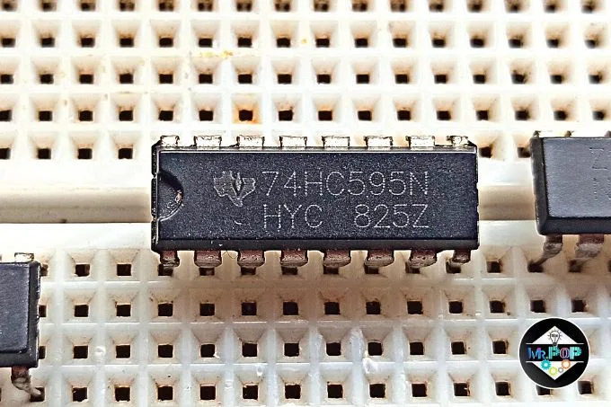
A 74HC595 has two registers: a shift register and a storage register. A shift register has 16 pins, but we only need three pins to control it, which are DS(Data), SRCLK(Clock), and RCLK(latch).
All outputs of a shift register are low at the start because there are no bits stored in the shift register. A data pin is used to sets the bits of an output pin to HIGH or LOW. Whenever the data pin is high, the bit is 1, and Whenever the data pin is low, the bit is 0.
A bit will be shifted into a shift register when the clock goes from high to low. Bits will push whenever it's on the rising edge of the clock, but the output will still be low because the bits haven't been stored yet in the storage register.
It is necessary to set the latch pin high to move bits into the storage register. The bits will update as its set in the shift register, for example, 10101101.
If you want to see the visual explanation of 74hc595 working, then watch this YouTube video.
74hc595 specification:
| Features | Values |
|---|---|
| Operating Volt | 2v - 6v |
| Power Consumption | 80uA |
| Output Volt | Equal to operating Volt |
| Output Current | 35uA |
| Clock Frequency | 25 Mhz at 4.5v* |
| Shift out frequency | 100 Mhz |
| Cascading | Possible |
Aplication of 74hc595 shift Register:
- Expand the GPIO pin of a microcontroller.
- LED Matrix/Cube Projects.
- Interface LCD.
- Cascading applications.
- High logic level controller.
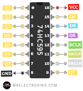
74HC595 Shift Registor Pinout:
2. GND pin :
Should be connected to the ground.
3. Q0 - Q7 pin:
These are 8 output pin of shift registers.
4. Q7’ pin:
It's used to add more shift registers by connecting Q7' pin to other ShiftRegister DS pin and send the same clock signal. With this technique, control as many LEDs as you like.
5. DS pin (Serial Data Input):
This pin is used to send data into the shift register.
6. SRCLK pin (Shift Register Clock):
When it's high, this means the data shifted to the shift register.
7. RCLK pin (storage Register Clock / Latch):
When it's high, the data will be updated and it's will move to the output pin.
8. SRCLR pin (Shift Register Clear):
It's used to reset the shift register.
a. When the pin is LOW means reset.
b. When the pin is high means no reset.
9. OE pin (Output Enable):
This pin is used to turn on or off the output.
a. When the pin is LOW means turn on the outputs.
b. When the pin is high means turn off the outputs.
Note: OE pin is also use as a pwm controller of all output.
Component Requirements:
Let gathering the component to build the arduino 74hc595 test circuit.
1. Arduino Uno to the control shift register.
2. A shift registers 74hc595 for controlling the LEDs.
3. 8 LEDs as an output.
4. 8 resistors to protect the LEDs.
5. Breadboard to make prototype circuit.
6. Jumper wires for connection.
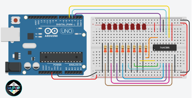
- The Arduino 5v pin should be connected to the 5v side of the breadboard.
- The Arduino GND pin should be connected to the GND of the breadboard.
- The power sides of breadboard should be connected together as well.
- A74hc595 VCC (pin 16) and SRCLR (pin 10) are connected the breadboard 5v side.
- A 74hc595 GND (pin 8) and OE (pin 13) are connected the breadboard GND side.
- Connect the 74hc595 SRCLK(pin 11) to pin 2 of Arduino.
- Connect the 74hc595 RCLK (pin 12) to pin 3 of Arduino.
- Connect the 74hc595 DS (pin 14) to pin 4 of Arduino.
- LEDs GND pin is connected to the GND side of the breadboard.
- Protect all LEDs from high current by adding a 220-ohm resistor to their positive terminals.
- The 74hc595 Q0 (pin 15) should be connected to the end of the LED 1 resistor.
- The 74hc595 Q1 (pin 1) should be connected to the end of the LED 2 resistor.
- The 74hc595 Q2 (pin 2) should be connected to the end of the LED 3 resistor.
- The 74hc595 Q3 (pin 3) should be connected to the end of the LED 4 resistor.
- The 74hc595 Q4 (pin 4) should be connected to the end of the LED 5 resistor.
- The 74hc595 Q5 (pin 5) should be connected to the end of the LED 6 resistor.
- The 74hc595 Q6 (pin 6) should be connected to the end of the LED 7 resistor.
- The 74hc595 Q7 (pin 7) should be connected to the end of the LED 8 resistor.
6. Let's get started with coding.
74hc595 Arduino Code:
int dataPin = 2;
int latchPin = 3;
int clockPin = 4;
//How many of the shift registers - change this
#define number_of_74hc595s 1

//do not touch
#define numOfRegisterPins number_of_74hc595s * 8

boolean registers[numOfRegisterPins];

void setup() {
  pinMode(dataPin, OUTPUT);
  pinMode(latchPin, OUTPUT);
  pinMode(clockPin, OUTPUT);
}
void loop() {
  for (int i = 0; i < 8; i++) {
    registersWrite(i, HIGH);
    delay(1000);
  }
  for (int i = 7; i >= 0; i--) {
    registersWrite(i, LOW);
    delay(1000);
  }
}

////////////function//////////////
void registersWrite(int index, int value) {
  digitalWrite(latchPin, LOW);
  for (int i = numOfRegisterPins - 1; i >=  0; i--) {
    digitalWrite(clockPin, LOW);
    int val = registers[i];
    digitalWrite(dataPin, val);
    digitalWrite(clockPin, HIGH);
  }
  digitalWrite(latchPin, HIGH);
  registers[index] = value;
  delay(5);
}
3. Upload the code.
4. After uploading is successfully, you can see LEDs is turning on one by one and then off one by one.
74hc595 Code Explanation:
int dataPin = 2;
int latchPin = 3;
int clockPin = 4;#define number_of_74hc595s 1#define numOfRegisterPins number_of_74hc595s * 8boolean registers[numOfRegisterPins]; pinMode(dataPin, OUTPUT);
pinMode(latchPin, OUTPUT);
pinMode(clockPin, OUTPUT);void registersWrite(int index, int value) {
digitalWrite(latchPin, LOW);
for (int i = numOfRegisterPins - 1; i >= 0; i--) {
digitalWrite(clockPin, LOW);
int val = registers[i];
digitalWrite(dataPin, val);
digitalWrite(clockPin, HIGH);
}
digitalWrite(latchPin, HIGH);
registers[index] = value;
delay(5);
}- Index - index of a Led.
- Value- Use to store state of led; high(1) or low(0).
digitalWrite(latchPin, LOW);digitalWrite(clockPin, LOW);int val = registers[i];digitalWrite(dataPin, val);
digitalWrite(clockPin, HIGH);registers[index] = value;
for (int i = 0; i < 8; i++) {
    registersWrite(i, HIGH);
    delay(1000);
}for (int i = 7; i >= 0; i--) {
registersWrite(i, LOW);
delay(1000);
}74hc595 Project Tutorial:
Wrapping up:
TAGS: 74hc595 8 LEDs tutorial, 74hc595 arduino, arduino 74hc595, arduino shift register, arduino shift register projects, 74hc595 pinout, 74hc595 projects.


Post a Comment